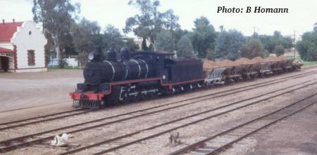
This is a series of 30 articles that were written during the restoration of original Ghan steam locomotive, NM25. The restoration took place from 2000 to 2003.
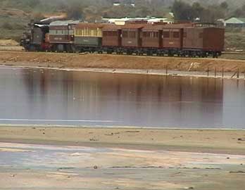
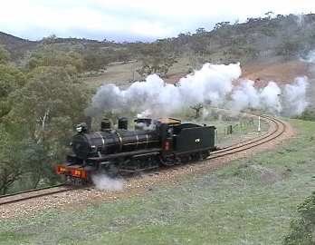
NM25 now hauls many of Pichi Richi Railway's heritage train journeys, on the same track it used to haul the Ghan for the Commonwealth Railways from 1925 to 1956.
Part 1: 1925 to 1990
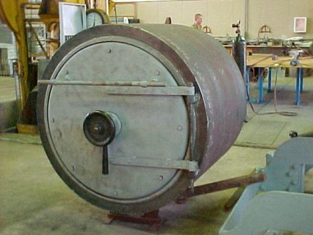
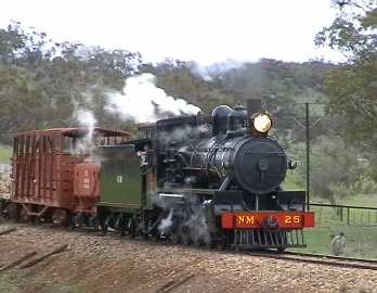
Pichi Richi Railway's NM class locomotive, number 25, is currently being completely restored.
NM25 is one of two surviving Commonwealth Railways (CR) 4-8-0 locomotives used to operate the Port Augusta to Alice Springs railway. The other (NM34) is maintained under cover as a static exhibit by the Port Dock Station Railway Museum at Port Adelaide.
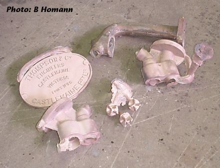
NM25 was built by Thompsons of Castlemaine (Victoria) in 1925, entering service in December of that year. It was one of the first batch of 14 locomotives of the class. A further 8 were subsequently ordered. They spent all their working life trudging up and down the line from Port Augusta to Alice Springs, with the exception of NM38, which was sent to Darwin, where it was apparently of little use, being too heavy for much of the track.
NM25 was one of the last to be in service, and survived, partly be cause it was kept as a standby to assist trains through the occasional flooded creek, when the NSU diesels could not get their traction motors wet. It was eventually transferred to Port Augusta where it maintained an existence as a stationary steam plant for cleaning at the roundhouse.
In the formative months of the Pichi Richi Railway Preservation Society, NM25 was considered for restoration. In fact a job costing was done by CR for a fitting a new boiler ex Queensland Railways (QGR). This indicated a cost in the order of $5,389, plus the purchase cost of $4,000 for the boiler. The Chief Mechanical Engineer recommended the Society against this course of action as he considered the boiler cost too high. In fact his memo infers he thought the price a bit absurd considering that the QGR were no longer using steam locomotives. In view of the fact that at the time a complete and operational 4-8-2 W class could be bought from the Western Australian Railways (WAGR), for a little over $2,000, his recommendation made perfect sense.
Thus the locomotive did not come to Pichi Richi, but instead went into the then wide open "Homestead Park" space in Port Augusta. It stayed there until 1990.
In 1989 the Port Augusta and Flinders Ranges Development Committee raised the possibility of extending PRR operations "from Woolshed Flat to Stirling North and possibly to Port Augusta". At the time there was also talk of moving the Yudnapinna homestead (at Homestead Park) from Port Augusta to Woolshed Flat. In the same letter, it was also reported that a member of the House of Representatives (Mr Tim Fischer) Standing Committee on Transport had made a similar suggestion.
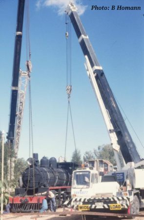
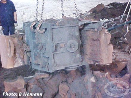
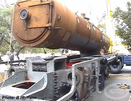
As a result of these suggestions, and the shadow over the future of Homestead Park, negotiations continued with the City of Port Augusta for the release of NM25. Eventually, it was exchanged for the remnants of a Broken Hill Associated Smelters 3'-6" 0-6-0 locomotive (Passchendaele) and ex Electricity Trust of SA 4'-8½" gauge diesel loco ETSA2. In an interesting day of big cranes and locomotives sailing through thin air, the exchange was made and NM25 arrived back in Quorn once again.
Part 2: 1990 to 2000
The locomotive sat in the PRR workshops, mainly being used as a talking point for visitors who needed to be impressed with the future possibilities of it running to Port Augusta again.
Progress at last
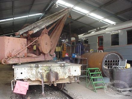
In mid 2000, funds were granted by the City of Port Augusta to enable the locomotive to be dismantled. This was to provide a more accurate condition assessment and rebuild cost estimate.
The overall rebuild estimate is now in excess of 50 times the boiler estimate of 1973. Just three months later, the funds are now available for the NM25 rebuild, PRR members have given the project the green light and we are about to embark on the great adventure.
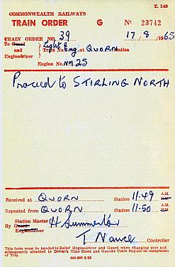
The target date for completion is 14 September 2001, just 43 weeks from the green light. Running in trials are then planned to commence, and the train order "Proceed to Port Augusta" will be able to written out for real.
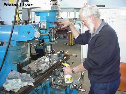
Part 3: December 2000
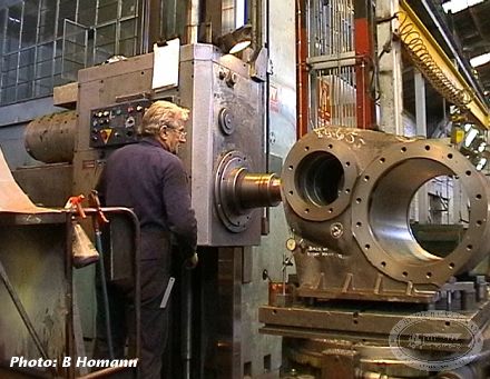
The main frame, axle boxes, some pallets of bits, and the cylinder boring machine are planned to leave Quorn in the afternoon of Wednesday 13 December.
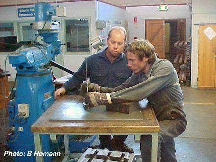
The main frame is going to Perry Engineering in Adelaide to be grit blasted and given one coat of prime paint. The remaining parts will go straight to the Panorama Campus of Douglas Mawson Institute, where the majority of work will be undertaken.
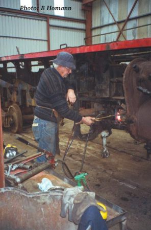
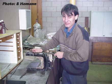
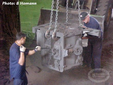
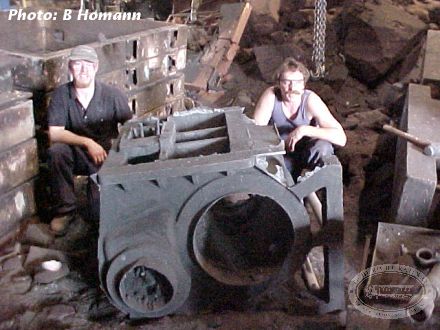
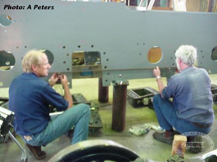
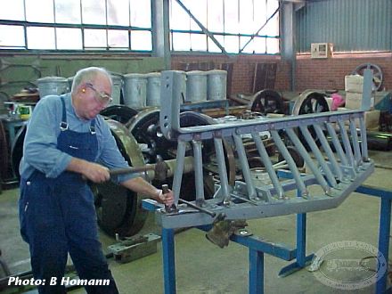
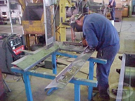
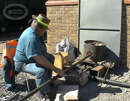
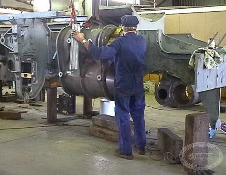
Two men are working at Quorn caustic bath cleaning components and palletising them for transport.
After the grit-blasting and painting, the frame will be moved to Panorama with the other parts.
Update: 18 December
The main frame, and the cylinder boring machine together with a couple of pallets of bits arrived in Adelaide the morning of Friday 15/12.
The main frame went to Perry Engineering for grit blasting and initial prime painting (so that it doesn't go rusty again!). Early in the New Year it will move to Panorama for work to commence in earnest.
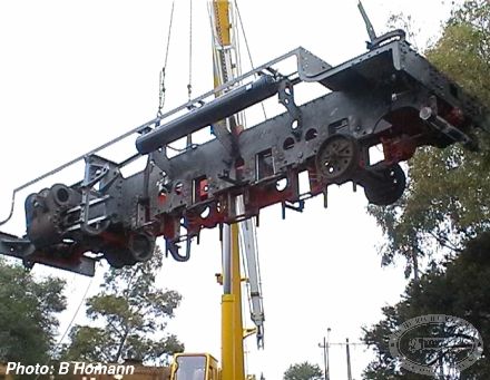
After some delays with transport, the frame was loaded using the two carriage jacks (on the front buffer beam) and the workshop overhead crane (on the cab end) to elevate it 1400mm into the air. The semi was then carefully backed underneath it on road 6.
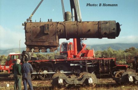
For interest, the load cell on the crane taking the frame off the truck in Adelaide indicated the frame weight as 8.5 tonne.
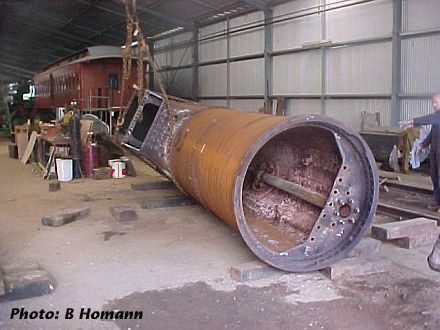
The boiler will be loaded in Quorn on Monday, and be sent to SteamRanger's Mount Barker depot, where the neccessary repairs will be carried out.
Part 4: January 2001

Investigations on the frames and boiler
The frame is now safely inside Panorama TAFE campus. The thorough grit blasting has revealed more evidence of a long and very arduous life. Most of the "light" items such as valance angles and running board supports have evidence of cracking, rewelding, cracking, stiffening and rewelding and more cracking! There will be a lot of new, rather than repaired, metal on the loco when it is finished.
The major concern at the moment is the cracking in the bottom of the LH cylinder. This appears to be a poor casting, with evidence of several casting defects, the most notable being blow holes and probable inclusions. Investigations are underway to determine if a successful repair can be done.
The boiler underwent non-destructive testing, involving around 38 gamma ray exposures and a load of ultrasonic and magnetic particle tersting. Immediate results from the ultrasonic and mag particle tests did not show any defects worthy of concern. The photos of the rivetted seams are yet to be developed and analysed.
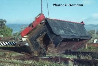
The tender and leading loco bogies have been stripped of their springs so that they can go for inspection and re-setting. The front tender bogie frame shows the scars of a severe impact incident, with the LH frame bent in interesting shapes.
Part 5: Boiler works—February to April 2001
Detailed investigations have revealed several serious issues with both the frames and the boiler of NM25. New frames, a new cylinder for the left hand side, and a new tube nest in the firebox end of the boiler are the major parts being priced at the moment.
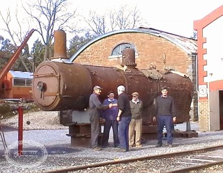
The boiler, which is located at the SteamRanger depot in Mount Barker, is being prepared for its rebuild. The primary reason the boiler is there is to provide ready access to SteamRanger’s pressure vessel welder. Extensive gamma ray photography has been carried out on riveted seams, together with ultrasonic and magnetic particle testing of welds. Unlike the frames, these tests have confirmed that structurally, the boiler is good. However, there is a lot of work being done, and still to do. At present, the surprisingly large number of studs are being removed. These have to be replaced because they are all very, very old, and in most cases very corroded. To add to the complication, there are known to be at least 29 different sizes of studs used on the boiler.
New super heater flues and smoke tubes have to be procured, swaged down and fitted. The tube nest in the firebox end tube plate is being replaced, due to cracking on the water side. Ongoing cracking on other preserved locos, has encouraged us to sort the problem out before returning the loco to service, rather than being faced with patch in a couple of years. At least part of the tubeplate has been replaced in the past, as evidenced by the weld repairs.
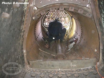
However, the major job is the replacement of around 95 of the 124 foundation ring rivets. These hold the inner and outer firebox wrappers together. Most of the rivets have lost their heads on the fire side, due to corrosion since trafficable days. We have arranged the use of a "squeeze riveter" for the insertion process. It is presently at Puffing Billy being prepared for a similar job on the boiler of Garratt G42. We are arranging to send people to Melbourne to assist Puffing Billy, and at the same time learn how to use the machine (they are learning too!). It may well see service on the main frames and bogie frames as well.
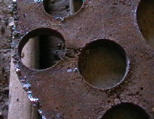
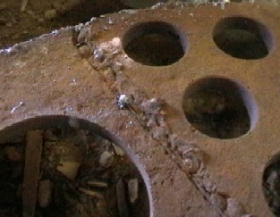
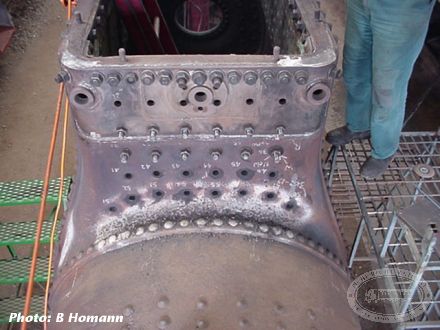
The firebox tube nest was cut out, and allowed acces for the first time in many years to the inside of the barrel. Having done that, we found that the small remaining piece of steel at the flange between tubeplate and crown of the firebox is very severely stress corrosion cracked all over on the water side. It looks a bit like a dried up claypan—quite horrible really.
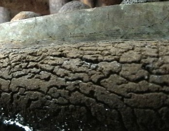
The metal appears to be too far gone to weld to, although grinding may help to determine how deep the cracking is (it looks deep). If it is too far gone, we will be faced with the possibility of having to remove it, weld up a look alike, and rivet it in place inside the boiler. This would be interesting as the space is limited, and two people will have to be on the water side to put the rivet in and set up the "holder on" dolly whilst someone else rivets up from below in the firebox. The work may be able to be done with the boiler upside down, but even that will present problems for the people doing the job.
While this has been happening, a new smokebox has been fabricated, due to extensive corrosion in the original. After a successful test fit to the boiler at Mount Barker, it is now back at Panorama for finishing. This will involve seal welding, cutting the hole for the funnel, and fitting items such as marker lamp brackets, handrails, headlight bracket, and the funnel.
Part 6: Frames—February to April 2001
The loco frame has just undergone extensive magnetic particle testing to check up on previous weld repairs. This followed on from heavy professional grit blasting after it came to Adelaide. It would not be an understatement to say that NM25 was sentenced to hard labour from the day it entered traffic, and that the sentence was rigorously enforced. The frames have been warped and cracked, welded and rewelded. Many of the welds are now shown to be cracked. This presents us with serious concerns about the long term viability of repair. We are aware of at least one case in heritage service where similar repairs have returned to cracks in a few years. Therefore, urgent steps have been taken to price compare the alternatives of repair or replacement. After doing this, and discussions with PRR loco and Executive people, it has been decided to make a new main frame. Whilst this sounds pretty radical, it will produce a far better long term result, for a relatively small additional cost over and above a repair job.
The left hand cylinder has (after the same grit blast job) shown up significant cracking due to a combination of poor casting quality, and an incident where it is believed the loco either took a short cut down an embankment, or suffered from a collision with an SAR T class loco. The cast iron smokebox saddle is also cracked, due to the tendency of the cylinder weight to pull the frames apart, and probably also the aforementioned incident. The fact that the QGR had gone to steel castings on the C17 probably says something. As with the frame, considerable effort has gone into evaluating the best options for corrective action in these vital areas. Accordingly, it is looking very much as though NM25 will be sporting one new cylinder. The right hand cylinder is somewhat newer, and is not expected to need replacement in this exercise. The saddle is likely to be strengthened using a patented metal stitching process, with assistance coming from as far afield as Mackay (QLD) and the USA.
TAFE have decided that building the new tender tank will be a great staff and student exercise. Accordingly, the tender underframe has been grit blasted and delivered to the Port Adelaide campus of Douglas Mawson TAFE, ready to provide a foundation for the new tank. Panorama campus are providing labour (at our cost) for a variety of metal fabrication jobs. This includes frame components such as a new rear drag box (the bit that connects the loco to the tender and therefore pulls the train along!), new smokebox, and new ash pan.
Two tradespeople, one metal trade trainee, and a part time trades assistant have been engaged, and are currently working on tender and loco bogies, spring hanger bushes and the like. Considerable effort is also being expended in getting components out to specialist suppliers for things such as grit blasting, spring repairs, and hard chroming. Items such as the all welded tender tank have required considerable engineering draughting work, to convert from the original riveted design, and to allow for currently available material sizes. To our horror, we have had to metricate some of this, because a lot of the modern world no longer has any concept of what an inch or a foot is. We have come up with a conversion that some modern people understand. A foot is roughly equal to the length of one school ruler!
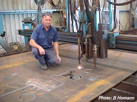
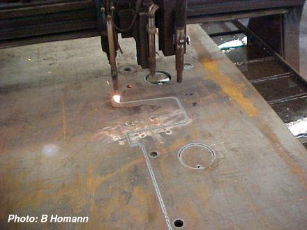
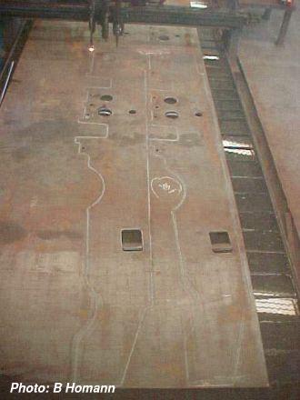
The new frames for NM25 were cut on 4 April 2001 at Adelaide Profile Services.
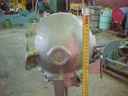
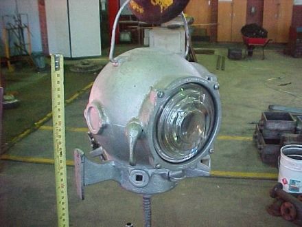
Part 7: Missing parts
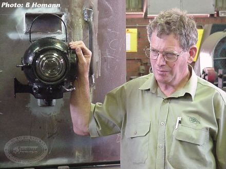
We are looking for two marker lamps to complete the set required for the locomotive. The pictures below show the two lens Pyle-National electric lamps as used by the Commonwealth Railways on these locos.
If there is someone out there who has a lamp that they would be prepared to donate to this restoration project, we would love to hear from you.
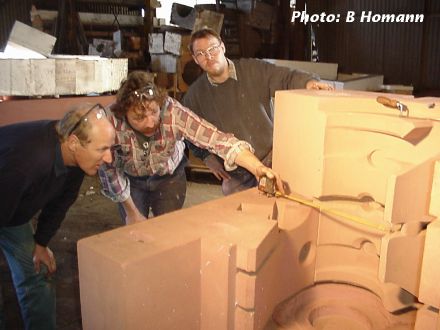
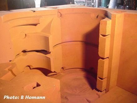
Part 8: Making a new cylinder—April 2001
New left hand cylinder
The pattern making work for the new cylinder/s is expected to be completed during the first week of May.
The cylinder will be cast on its end, thus the sand mould made from the end of cylinder core box will become the base upon which all will be built. There is in fact no pattern item that represents the actual outside shape of the cylinder in its entirety. Basically, the process is to have shaped boxes in which blocks will be made from self setting foundry sand. This will create a set of strange shaped lumps of sandstone which will then be assembled, like a 3D jigsaw puzzle, to form the outside shape of the cylinder as a hollow space between them.
A similar process will be employed to produce the sand pieces (called cores) that create the holes through the casting that will be the main bores, and the passages for the steam to go in and out through. These are progressively fitted into the hollow described above as it is all assembled. Once the whole lot is assembled, it will be surrounded by dry sand to hold it together ready for the metal pouring business.
Boiler work update
The boiler has finally reached the point where there is no more metal to be removed. Metal is in fact being reattached, with various corroded areas being built up by layers of electric arc welding in a process called "pad welding". New boiler plate has arrived, and the process of preparing it for insertion is about to begin. The welding procedure test welds have been done, and all that remains before we can go ahead here is completion of the mechanical tests to qualify (and thereby approve) the repair processes.
The many replacement parts such as new stays and studs are in the process of being made. The next major step is to complete the steel former to form the flange for the portion of tube plate being replaced (damage shown in Part 5), and to then beat a 12mm piece of boiler plate to the required shape. Fortunately winter is upon us, as this will be a hot and muscle toning exercise!
Cab, frames etc.
The cab is now almost complete, as is the smokebox. Design and drawing work is almost complete for the new main frame assembly, and assembly of this could begin in the next couple of weeks. The trailing driving wheel set has been re-assebled with its new axle, and setting up for reboring the crank pin holes is scheduled to happen in early May.
Part 9: Boring the crank pin holes—May 2001
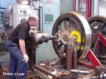
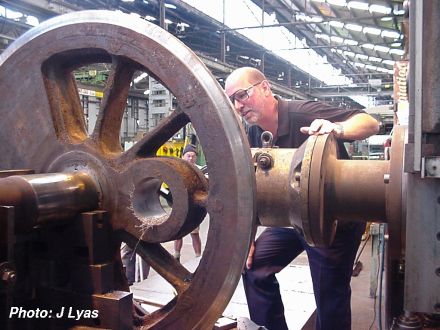
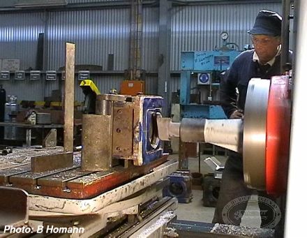
This update contains a couple of photos showing the crank pin holes being bored on a horizontal boring machine at Perry Engineering Division of Air Ride Technology. The second set was completed on Tuesday 1 May, and all four should be complete by the end of the week. During setting up for the quartering process (done by co-ordinate measurement on the machines' digital readout system) the two sets of wheels done so far were found to have a difference in quartering angle representing about 1mm at the crank pin. This would not have been conducive to good bearing life.
Part 10: Putting it back together—May 2001
Rivetting bogie frames
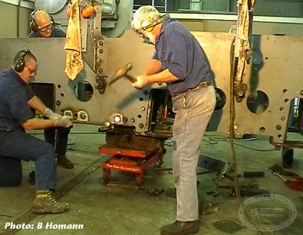
Perhaps the title Putting it back together is a little early yet, but progress has started in the right direction. At one of the regular volunteer nights recently, the frame for one of the tender bogies, which had been partially dismantled for straightening, was drilled ready for rivetting back together.
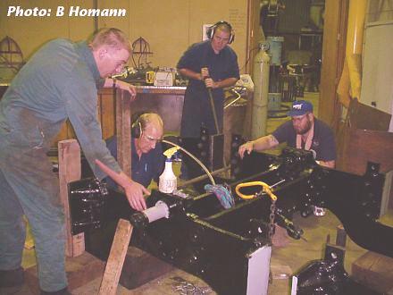
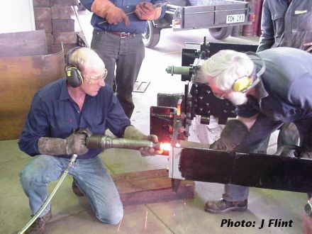
After the holes had been drilled, the noisy and dirty task of inserting and squeezing hot rivets began. The rivet is heated to white-heat in a forge, inserted in the hole, then with some teamwork, squeezed in to hold the two plates tight together.
One person holds a "dolly", which is not a child's toy! It is a large, heavy steel block, which is held against the rivet head, to stop the rivet falling out, and hold the head hard against the plate.
The other person operates an air-powered impact gun, which gradually compresses the "blank" end of the rivet into the hole and countersink in the other plate.
The rivets we're using here are about 7/8 inch (22mm) diameter, and require about 10 seconds of impacting before they are "cold". By cold, we mean that it is no longer red-hot, and has begun to harden and shrink in its hole. This shrinking puts the greatest squeeze on the plates being held together.
Part 11: Wheels, bearings and frames—May 2001
Wheels
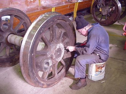
The driving wheel sets have now come back from having the crank pin holes requartered on a large horizontal boring machine. The quartering was found to be at some variance between wheel sets before boring. They are now supposed to be within a couple of "thou of an inch" of each other both radially and angularly. The wheels are now being cleaned, and below the muck, have revealed Thompsons of Castlemaine cast into the inside of the rim.
Bearings
White metalling has also been proceeding, with all the tender and pony truck brasses having been now re-metalled. Next step is to bore these to size and fit them to the journals.
Frames
The order has been placed for machining and welding the new frame together. Completion is anticipated toward the end of June.
The stress analysis drawings previously available here are now on the next page.
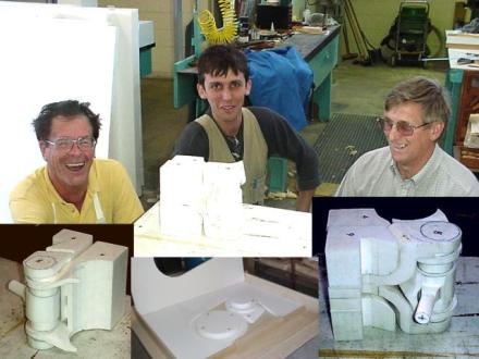
Cylinder update
As of 11 May, the core boxes for the cylinder pattern are now complete. The styrene foam model of the internal coring shown in one of our photos has now been adorned with the external sand shapes to assist the moulders with the jig saw puzzle. Building the moulds should commence in Mid May.
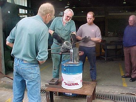
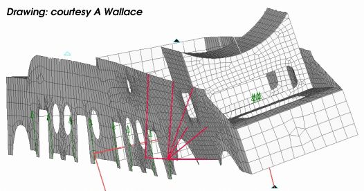
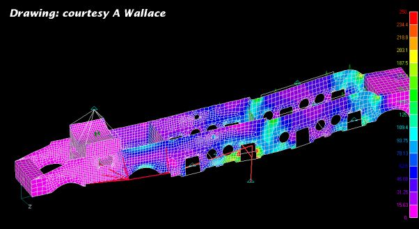
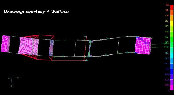
Part 12: Frame stress analysis
Allan Wallace, a mutual friend of John and Bryan, has kindly donated his expertise to carry out finite element analysis of the proposed new frame structure. He has also completed a similar analysis of the old frame.
Whilst the stress model allows for axle loadings, drawbar pull and piston loads, it is not refined to the extent of allowing for dynamic stresses. However, the main purpose was one of comparison, and this demonstrates that much of the high stress in the original frame is considerably eased in the new. It is comforting to note that the predicted high stress points correlate very well with the actual crack locations in the old frame.
The pictures shown here are extracted from the computer modeling program. It would be interesting (and a little bit scary) if we were able to show the contortions of the frame as the stresses vary.

Part 13: Wheels, axleboxes, frames and tender—June 2001
Cylinders
After discussion within the PRR Locomotive Department, it has been decided that both cylinders will be replaced. Moulding for those continues.
Wheels
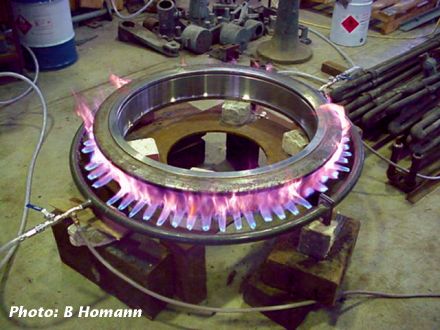
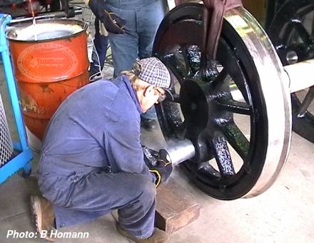
The tyres on the tender wheels needed to be replaced, and after the removal of the old tyres, and cleaning of the wheel centres, the time came to fit the new tyres. The age-old method of heating the tyre to shrink it onto the wheel centre had to be revived, and SteamRanger had built a large gas ring for doing the same job to their locomotive 520 a few years ago. We needed to make our own, due to having far smaller wheels, but the principle was the same. After design started early Wednesday morning (13th), construction of the ring took place through the day, and the first tyre was successfully shrunk on at 3.30pm. Three more were done by PRRPS volunteers during the regular Wednesday Volunteers Night, and the remaining four were completed on Thursday 14 June.
The process is quite simple. Prior to heating, the wheel centre and the new tyre must be machined such that the tyre's inside diameter is slightly smaller than the wheel centre's outside diameter. This difference causes the tyre not to be able to be fitted, but once it is fitted, means that it is held on there, and will not come off except in extreme circumstances. To get the wheel centre into the tyre, either the centre must be shrunk, or the tyre expanded. Considering the cost and quantity of liquid nitrogen (or similar) that would be required to cool the centre enough, it is by far easier to heat the tyre.
Heating the tyre takes between 10 and 15 minutes with the gas ring, which causes it to expand enough that the centre can be placed inside it with an overhead crane, and the whole lot allowed to cool. In the cooling process, the tyre shrinks back to near its original size, and in the process, clamps itself to the wheel centre. Care must obviously be taken to ensure that the tyre and centre line up and sit together properly.
Axle-boxes
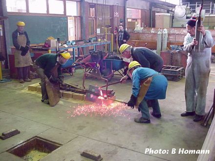
After the torrential rain on Wednesday 8 June, and other water related disasters, all of our moulds prepared for new bearing brasses were ruined by the flood waters.
Failure of the cooling tower (water leaks from the closed water circuit) on the induction melting furnace meant that the old oil fired pit furnace had to be resurrected. Thursday 14 June saw this do its first melt in nine years, with the manufacture of the first half of a set of phosphor-bronze liners for the tender axle-box slides. The furnace sounded just like our oil fired T class loco (and smelt much the same!)
Frames
The new frames are currently being machined, and following completion of that, they will be assembled.
Tender
As mentioned in an earlier installment, the whole tender tank is to be replaced. Construction of this is being done at Port Adelaide TAFE campus, and is well underway.
Part 14: Frames, boiler and other parts—July 2001
Frames
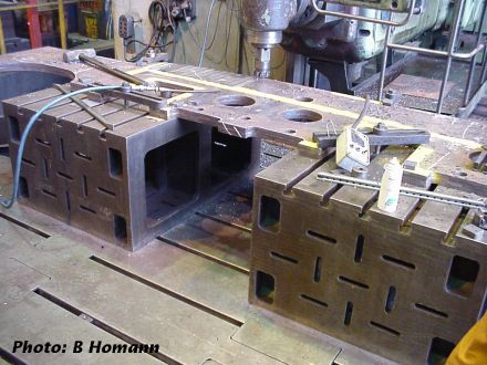
Drilling of all the major mounting holes in the frames is complete. The new cross stretchers are in the process of being machined.
Boiler
After finding further cracking in the throat plate immediately above the foundation ring, it was decided to remove the bottom 11 inches of the throat plate. This has enabled another troublesome area, the front mud holes, to be dealt with. This is being done by way of welded in sockets for washout plugs.
Along with a flanged section for the top of the firebox tube plate, replacement throat plate steel has been hot formed to shape. This involved a large amount of LPG and oxygen to provide the heat, and the use of heavy wooden mallets to belt the steel into shape. Wooden mallets are necessary to avoid bruising the steel when bright orange hot.
One of our retired members who no longer gets to Quorn, Charlie Rosewarne, enthusiastically assisted with the provision of timber, shaped for mallet heads.
The new flange piece for the firebox tube plate has now been fitted, and is in the process of having the rivet holes drilled. Test riveting has been carried out to provide the boiler inspector with samples of our work.
The new longitudinal stays have been manufactured from bar stock which has then been built up at each end by pad welding. We decided on this method as we could find no-one handy who could upset forge the ends for us. These are now being proof machined for magnetic particle testing,and will then be screw cut ready for insertion.
Other bits and pieces
The cylinders are dragging their heels a bit, but moulding has commenced preparatory to casting them.
We have cast new tender axle box bearings on site, as well as new phosphor bronze axle box horn slides. These have been machined on site and the bearings white metalled.
The cab roof timber work has been largely completed by students from Marleston campus of Douglas Mawson TAFE.
During one particularly wet evening, we suffered a minor flooding of the work shop. The biggest casualty was the moulds for the new axle box bearing castings. These all had to be re-made.
The tyres have been shrunk onto the tender wheels using a home made gas ring. The pony truck has now been re-assembled and awaits a locomotive to support.
Bryan and John visited Puffing Billy Railway to gain some insight into the use of the squeeze riveter that they (and now us) have borrowed from Barry Tulloch of NSW. The riveter has now arrived at Panorama and will be soon put to work.
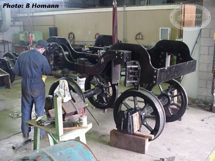
Part 15: Frames delivered, boiler work continues—August 2001
Frames
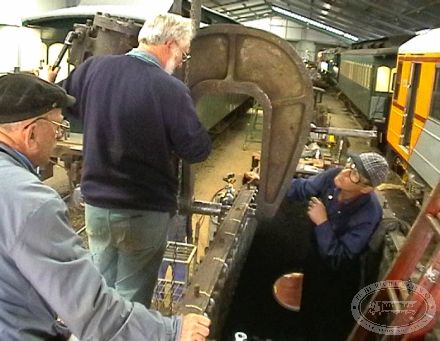
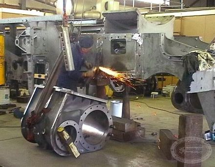
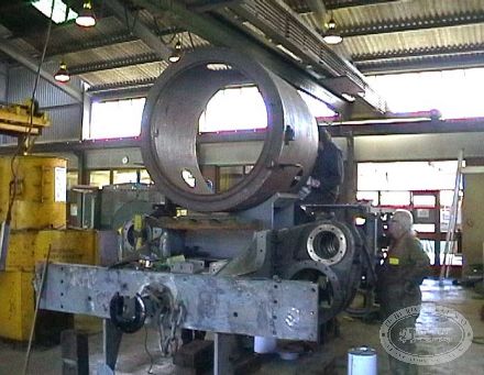
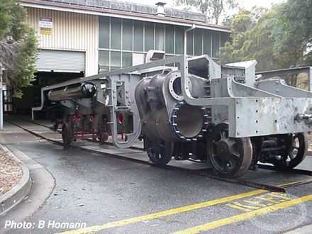
The most exciting thing to happen recently has been the delivery to Panorama TAFE of the new all welded "super" frame. The new design of frame stiffening can be seen. However, the solid looking plate where the firebox is to go (at the end closer to camera) will be partly removed. That centre was left in to assist in stability during the welding process, and to ensure that the material came to us! The first job is to clean the frame down for painting, most of which is likely to be done by volunteers.

Boiler
On the same day, the boiler was inverted to prepare it for foundation ring riveting. The new sections of the throat plate and firebox tube plate have to be welded in prior to the riveting, and inverting the boiler will make access to the job far easier, as well as providing for better fume extraction.
Tender frame
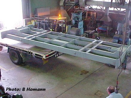
The next day, the tender frame arrived at Panorama from the Port Adelaide TAFE, where it was used as a jig for the laying out of the new tank. The stiffening transom plates above each bogie location are currently being riveted back in position. This is providing an opportunity to practice our skills with Barry Tulloch's squeeze riveting machine. Our success score was not too good initially, but the strike rate is improving.
Other activities
Whilst the paid work force has been temporarily reduced due to some budgetry problems associated with level crossing protection devices for the Stirling North to Port Augusta link, work is still progressing, with volunteer assistance still well evident.
Part 16: First new cylinder is cast—September 2001
One year after the dismantling of NM25 was commenced, the project has moved forward a long way, with the casting of the first of two new cylinders for the locmotive.
As mentioned on earlier pages, one cylinder was in poor condition, and the decision was taken to replace both while the loco is being rebuilt. After several months of pattern making and moulding, Monday 17 September saw the mould sitting in its pit, and almost a tonne of molten iron poured in.
The saying goes "The proof is in the pudding". In this case, the pudding needed two days to set, before it was extracted on Wednesday 19th.
Tender frames
Since their delivery last month, the tender frames have gradually had the various fittings attached, with a lot of the work being done by volunteers.
Part 17: Tender and boiler update—October 2001
Tender
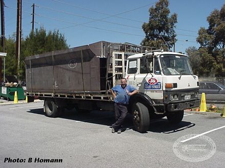
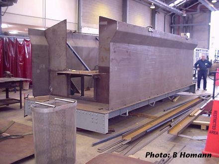
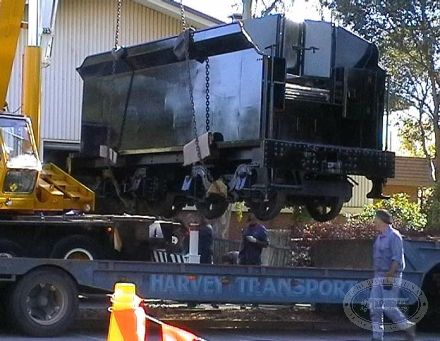
Wednesday 7 November, the tender underframe was turned upside up. It had been upside down to facilitate plate riveting and air brake repiping (all brand new) during October. It was then married to its bogies. The tender tank, which was built by staff and students at the Douglas Mawson Institute of TAFE Port Adelaide Campus, was delivered via our friendly transport man Robert Johnston (he is the bloke leaning on the truck in the delivery photo). This was placed on blocks on the tender frame to facilitate painting of the tank underside.
Boiler
Boiler repairs have progressed to the point where the new section of throat plate is fully installed (except rivets and stays). The new flanged piece of the firebox tube plate, and the lower plain section of the same tube plate have also been welded in. Curently, the smokebox tube plate is being welded in.
It is intended that on Monday 12 November, we will commence the process of installing the new foundation rivets. The squeeze riveter has been delivered to Mount Barker. The riveting process will involve both Pichi Richi Railway people and SteamRanger people. This is partly because the work is being done at the SteamRanger workshops, and also because they also want to gain knowledge of the riveting business.
Part 18: Boiler rivetting—November 2001
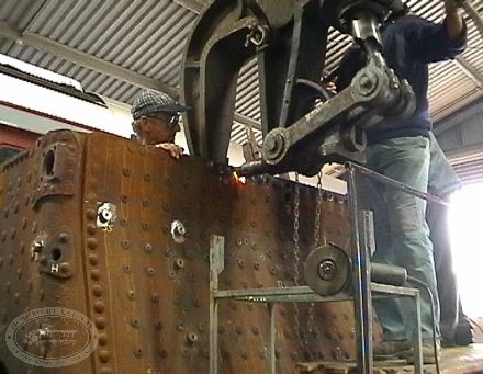
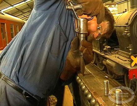
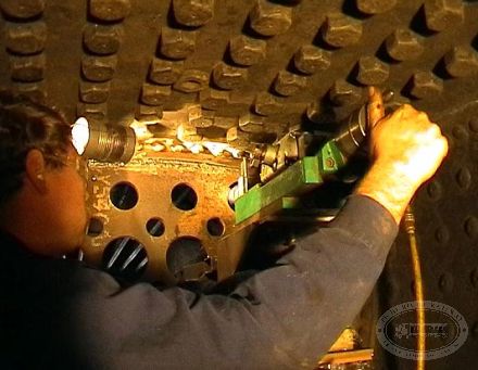
We commenced installing the foundation ring rivets during mid November. Using Barry Tulloch's squeeze riveter makes this about the easiest part of the rivet replacing process.
After all the effort of drilling and burning out the old corroded rivets, heating new ones up, slipping them in the hole and flicking a ball valve to get a satisfying clunk as the riveter bottoms out is a breeze. We have the riveter hanging on an old broad gauge 5 ton hand operated crane which is barred along a track parallel to the boiler to move from one rivet hole to the next. Height adjustment is by a 1 ton chain hoist hanging on the crane hook.
Part 19: Various work updates—December 2001
Workforce update
Advice has been received that the rebuild project can continue at its former pace. Accordingly, the work force is now being rebuilt.
Boiler
Since the foundation ring riveting, work on the boiler has concentrated on completing the welding in of the smokebox tube plate. Following that, the new flanged section of the firebox tube plate was riveted to the copper crown sheet. During this process, some pitting of the manufactured rivet heads was noted, and after careful examination, it was decided to remove them again and carry out an investigation into the causes.
Accordingly a series of test rivets were inserted into test bars. Whilst some pitting was created, there was nothing like that found on the rivets in the boiler. These tests tended to indicate that the popular theories of over heating of rivets, or scale in the rivet snaps was not a major contributing factor. We did observe some changes with different rivet snaps. Spectrograhic analysis and mechanical property tests did not indicate anything untoward in the material. After detailed discussions with our boiler inspector, it was agreed to try again.
Work has commenced on the grate supports, and the new ash pan.
Frames

Another problem that requires a solution is the "fish bellying" of the boiler halfway along the firebox. If left un-attended, this means that the boiler will not fit between the frames! The reason it fitted the old frames was that constant battering over the years had caused the frames to bend outwards and rub against the back of the wheels!
It looks as if the solution will be akin to putting a big G clamp on, and tightening up. It may be that a device similar to a trackman's Jim Crow will have to be made.
Concurrently with this investigation, small warps in the all welded main frames have been relieved out, and it stands ready to receive paint and axle box horns. Both new cylinders are now cast, and are expected back from the machine shop around Christmas.

Tender
The tender is looking fairly complete, with the tank now bolted to the underframe. "Second fixings" are now happening, with hand rails, hand brakes and the like being fitted.
The volunteers who work on this on Wednesday evenings are divided into South Australian Railways and Commonwealth Railways supporters. When they are not painting, they appear to be engaged in a battle to come up with the best (or worst) words that might match the CR which will be painted on the side. Examples include "Competent Railways" and "Constantly Rusting". The unpainted tender sides are sporting several "thoughts" on what CR means!
The foundry has been put to use again, with some pipe brackets and the fire-door protector plate being produced in cast iron.
Part 20: Various work updates—January 2002
Winding down
To conclude the year 2001, a bar-b-q tea was held at John Lyas' home just prior to Christmas. This was well attened by staff and volunteer workers alike, and a pleasant eat was had. When darkness fell, John's father produced a 16mm projector and screen. After getting a big laugh from a couple of Abbot and Costello golden oldies, we had a look at some excellent footage of NM25 on its last operations in the 20th century (back in the 60s).
Riveting work
As indicated in the December notes, we had decided to give the crown sheet riveting another go. After all the tests, where we were unable to reproduce the pitting problem, the very first rivet inserted in the second round had them. To use a good Aussie expression, "bugga"!
Fortunately it was close to morning tea time, this providing an opportunity to think again. John Lyas made a throw away comment that he thought the last rivets of the first try were not pitted as badly as the rest. It happened that these four rivets were held up manually, using a long lever (Archimedes would have been proud!), whereas the others used an pneumatic "holder up".
Some mental arithmetic whilst gazing into the tea cup indicated that it was probable that we were able to exert more force manually, than with the pneumatic device. In fact, as we had Gordon, one of our sturdy boilermakers, with us, it was decided to try the lever again using the combined efforts of him and John. To our surprise (and great relief) this worked. Quantifying the experiment means that a successful job can be done using 1.6 "Gordon power" on the bar, John being less substantial than Gordon.
This would appear to conclude the rivet experimenting. We can only surmise that the pneumatic holder up had insufficient force, combined with a tendency to bounce in the early stages of the riveting. With the metal being close to melting, perhaps the vibration combined with contraction due to snap contact literally shook the head apart. The firebox tube plate top corner is now securely in place.
Boiler repairs
The copper main steam pipe from the regulator to the smokebox tube plate had to be removed to effect a good braze repair to the collar where the regulator gooseneck attaches.
At present, the joint between the foundation ring and the outer firebox wrapper is being completely seal welded. The reason for this is the concern that weeps might start there after a few steamings. Due to the nature of in-between-the-frame boilers, this area is generally inaccessible for caulking once installed on the loco.
New holes have been drilled and tapped in the foundation ring to provide a means of fitting angles to support the grate side bearers. This will make the grate system in this loco the same in principle as the W class, resulting in the ability to use the same grate fingers in all our coal fired locos.
Machining of the new boiler longitudinal stays is almost complete. Because we did not have ready access to the means of upsetting the ends to provide material for the heads and threads, this was achieved by "pad welding" the ends up to size. After proof machining, these were 100% magnetic particle crack tested.
Marking the frames
Back at Panorama, the main frames have been marked out to identify cylinder, axle and other motion attachment point locations. In the process of doing this we discovered that the welding of the frame had shortened the distance between the driving axle horn cut out and the cylinder centre by about 3/32". To avoid messing with the motion work, the cylinders are being machined with the mounting holes offset to take account of the variation. It is interesting to note that on coolish days when there is some sun radiation into the building, the top of the frame becomes marginally hotter than the bottom. This causes the frame to "hog back" such that the centre supports actually become free of load by up to 1/8".
Work is continuing on the manufacture of the new ash pan and the ash deflector skirt that bolts to the boiler foundation ring. The various angles and assemblies that support the running boards are being fitted to the frames. In most cases, these will be riveted, as per the original. The horn stays are being progressively fitted to the frames. Even here, problems have arisen due to the welding shrinkage of the frame. In the case of one horn, it was found to be considerably "un-flat" where it faces onto the frame. This was due to cracking and subsequent reweld when it was not properly lined up. No doubt the condition of the original frame had a bit to do with this, as the welding would have been done in-situ, probably under difficult access conditions. It is yet another part that has had to be re-worked.
Tender and marker lights
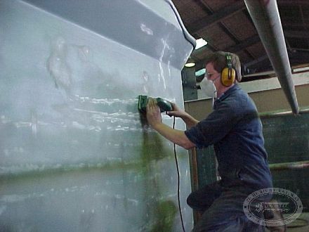
Volunteer input is picking up again after the Christmas recess, with the tender tank being fully sanded down ready for painting. In the near future, more volunteer foundry and riveting work will be happening. Our website "ad" for marker lamps has been successful, with a full complement of 4 now available. It would still be nice to have a spare, so the request is still open.
In early photos, the NM's are frequently shown with a single marker at the front and rear, and sometimes with two at each end. We do not know if this is due to some policy change in CR, a shortage of lamps, or what. If any one knows the answer, we would be delighted to hear from you. Someone suggested that the different usage reflected route indication. Given that the NM's went either north or south over the one route available to them, route indication would seem to be a bit unnecessary. Train ID might be a more plausible reason (goods, passenger etc).
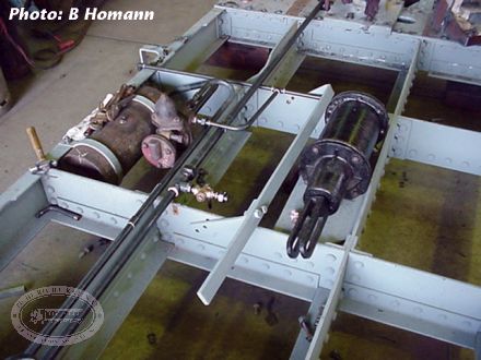
Part 21: Ashpan door cylinder, and axlebox covers—January 2002
Ashpan Door Cylinder
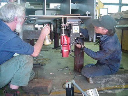
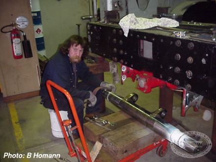
To make life a little easier for the crew, the ashpan doors, of which there are three, are operated by an air cylinder, rather than the more traditional "1 Fireman Power". Obviously the cylinder needs to be fixed to the frame, so the magnetic base drill was put to use to drill the mounting holes.
Silver axlebox covers
It has been a long standing thing with John Lyas, that he does not like axle boxes picked out in bright colours. Thus he has been less than keen on the silver axle boxes that adorned NM25 when we got it out of the park.
To stir John up, the Wednesday night volunteers got to work early last volunteer night and encased the axle box covers in aluminium foil. It took three trips past the boxes before they were noticed!
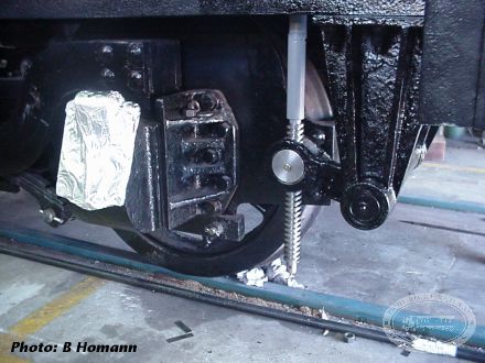
This photo shows one of the aluminised boxes, together with a beautifully machined 2tpi square form thread and nut for the tender hand brake. This was machined as a volunteer job by John Buckingham. Some people reckon they have it made with three tenors. We have twice as many Johns! There is boss John Lyas, fitter John Pudney, boiler maker John Willis, volunteers John Southwell, John Buckingham and occasionally John Wilson and Jonathan Thompson.
Part 22: New cylinders delivered, and assorted boiler work—February 2002
Progress has been steady, rather than spectacular during most of this year.
New cylinders, and frame work
The new cylinders have been received at Panorama, fully machined and ready for installation.
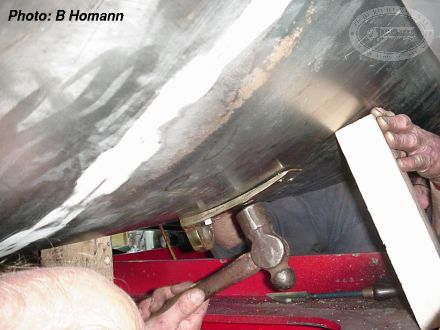
A great deal of effort has been expended on the fitting and fixing of the axle box horns and the spring compensating gear. This virtually un-noticeable task has required the location of the horns and compensating beam brackets, and reaming over a 100 1"+dia holes. This has been a combination of lugging a heavy magnetic base drill inside the frames for initial sizing by drill, and laborious hand turning of the reamer to finish off. These holes are now being filled with fitted rivets. These are a hammer press fit in the holes when cold. The ends are then heated up and riveted into counter sunk holes by two men wielding hammers. This has taken a bit of practice, and on only a few occasions so far have we been able to meet the standards of yesteryear where the riveting over was achieved in one heat. However, there are plenty more to do, so the skill level will improve.
Brackets to hold up the running boards have simultaneously been fitted, this time by hot riveting. Once again there have been many holes to drill, with the mag base drill having to be set up sideways. In a few cases, for the ashpan door operating cylinder location bolts, the drill was upside down. Drilling was done in the fervent hope that the power did not go off.
The brand new ashpan has been fitted, and then removed to allow finishing of its doors, and to allow room for the afore mentioned drilling and reaming works.
Because of the need for access for drilling, riveting etc, it has been necessary to hold back the fitting of important looking items like cylinders. The hammering is difficult enough, without having to lean over great big castings.
It has been slow and demanding work, for which there is little to visually show.
Work has commenced on some components in the motion and reversing gear. Even here, it has been slow work, with virtually every hole having to be rebushed. In some instances, this requires the component to be set up for boring the hole true, then a new bush produced and case hardened. Once this is done, the pin or bolt that goes in the hole generally has to be renewed and be heat treated. None are "off the shelf" items.
Boiler work at Mount Barker
The boiler has been the scene of continuing frustration. The firebox, in the region of the foundation ring, has fishbellied over the years such that it pushed the frames apart! One symptom of this was the crescent shape grooves worn into the frames by the wheels! Initially, we thought this frame movement was all due to lack of support and the bashing received as the boiler slipped from side to side during its many voyages to Alice Springs and back. Certainly the rivet marks in the old frame plates suggested that. However, it seems that slow creep of the boiler itself also provided unrelenting pressure.
Because the new frames are the size and shape they are meant to be, and because we do not want to repeat the problem of the wheels rubbing against the frames, it has been necessary to try and straighten the firebox. Initial calculations indicated that a squeezing force of 20 tons would be adequate to achieve the desired straightening effect. They were wrong! The first try did straighten the firebox, but only elastically, so it went back whence it came when the load was released. With the benefit of some hindsight, a finite element stress analysis was done which confirmed the "after first try gut feel" that 30 to 40 tons was going to be required.
While putting this sort of squeeze on the boiler seems all wrong, there is no alternative short of removing the firebox and starting over again. We would require a rich benefactor to enable the project to go that far. Work is in hand for the boiler squeezer MarkII.
There is, however, some positive progress, with the new longitudinal stays being fitted. Whilst doing this, a copper stay was noted as looking decidedly peculiar in its relationship with the plate it was screwed through. Consultation with the boiler inspector concluded with a decision to replace it, and possibly two others. Once this particular problem is resolved, the final piece of plate, the firebox tube nest will be ready for welding into place. A small portable boring machine has been made to finish some of the tube holes that had to be left undersize due to closeness to the weld line. This has been tested on the draw bar pin location below the cab floor where existing profile cut holes had to be trued up to take the draw bar pin bushings (new naturally!). This same device will be used to true up and align the location for the reversing shaft in the frames.
Part 23: Boiler squeezing—March 2002
The firebox fish bellying, which had caused a lot of headaches (and would have prevented the boiler going back into the frames), now appears to have been cured. Initially, we had tried a 20 ton squeeze on the foundation ring area, but found that we were not achieving yield point for the material. As our first estimate of the effect of the rest of the boiler was clearly not right, we sought help from our friendly finite element analyst. The compute showed the stress effects going further into the boiler, (and to a minor degree, appearing a long way from the point of application). The analysis predicted about 30 tons being required.
Another helper provided a set of detailed calculations and sketches for a 40 ton capacity squeeze frame. In effect this is like a giant hydraulically driven G clamp.
With some trepidation, the first squeeze was applied to the centre of the foundation ring. Careful measurement of hydraulic pressure, and boiler deflection were carried out as the load was gradually increased. In effect this became a stress/strain diagram which enabled us to determine when the boiler ceased behaving elastically, and began to yield. It was interesting to note that the person operating the hydraulics could "feel" the change from elastic to plastic, this being confirmed at the next measurement step.
Several squeezes were required, sometimes using a piece of rail to spread the load on one side to direct the yield to one side only. The final result is a remarkably straight foundation ring, which is smaller than the width of the frame insides. It is probable that a few rivet heads will need to have a bit removed when it comes time to fit the boiler to the frame.
The new longitudinal stays have all been fitted and adjusted for length.
We are now, finally, at the point where the firebox tube nest can be welded into place.
Part 24: More boiler work—April–May 2002
Finally, after the squeezing of the foundation ring, the last major piece of welding was able to occur. This was the fire box tube plate. Once this was in place, and most of the welding done, it was close to time to put the boiler back up the right way.
We are finally getting to a point where progress will appear to be accelerating, simply because most of the work that has to be done in serial fashion is complete. Just prior to "flipping" the boiler over (in the trade, big items always seem to be "flipped" as if they were the size of a dollar coin!), the throat plate stay holes were reamed to final size, and threaded. This enabled the installation of the stays that had been in store for some months. The final upside down jobs”were the fitting and tacking together of the grate support angles and the ash deflector skirt, and caulking of the firebox copper plate to the foundation ring.
The boiler was then duly flipped, enabling easy completion of the tube plate welding.
Whilst this was occurring, the boiler tubes were taken out of storage to be readied for installation. The superheater flues were trimmed to length and put out side to have their ends annealed. The small tubes (which had been swaged down at the firebox end and cut to length at Quorn many months ago were also got out. Two of these were placed in the boiler to help provide a shelf to support the portable boring device required to open up some of the fire box tube holes. Super-embarrassment when we discovered that these tubes were about an inch short. Length was according to drawing, but not according to boiler. Not sure what happened, but it seems like there might have been a bit of dyslexia when writing down the measured length last year, causing the right dimension to be written down wrongly, and then discarded as being wrong, causing reversion to the drawing. Whatever the reason, it had to be fixed, so a piece was cut off each tube, and a slightly longer piece welded on. Sometimes when you make a mistake you pay once. Here we paid 70 times!
Current state of progress is that the re-ending process is well advanced, most tubes have been annealed, and about half the superheater flue tubes have had their ends polished. The throat plate stays have been seal welded, and it remains only to weld in one bush (for the pressure gauge connection) for weld repairs to be complete.
Because some of the tube plate holes are close to the weld line, it was decided to cut these (in the case of small ones), and open up (in the case of big ones) after installation. This was accomplished easily on the smoke box end using a magnetic base drill for the hole making. Four of these holes had to be taper tapped for washout plugs. Here a support was tacked to the smokebox ring to guide the tap, and a ratchet spanner in concert with a long piece of pipe did the screwing. Opening up the super heater flue holes in the firebox tube plate has commenced using our homemade air powered boring machine. It is a bit of a grunt to get into position, but is doing a satisfactory job.
While all this has been going on, work has commenced on cleaning up the mounting faces for the various boiler fittings. Installation of the tubes is now only a matter of hours away. That means it will be hydraulic test time very soon. We are keeping our finger nails long for biting on!
Part 25: Fitting the cylinders, and (almost) finishing the tender—April–May 2002
Work has been going on to install the running boards. Whilst, in loco terms rather tin plate type material, it has added a noticeable bulk to the frame.
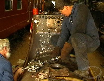
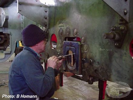
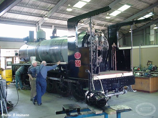
In parallel to this, we have obtained some helpful advice from a long retired Islington Works erecting shop foreman on setting up cylinders. Because there is some inevitable weld induced distortion in the frame, it is necessary to offer up the cylinder, smeared with bearing blue, see where it touches, and grind off the high spots until an even “print” is obtained all round the bolting flange. This has taken some time, with the cylinder having been put in its place many many more times than once. Once this time consuming job is complete, the final alignment of the cylinders can be done, and work can commence on setting up the axle boxes, and ultimately the wheels.
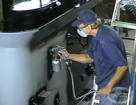
The tender has been fully painted in its final glossy black coat, and has been transported north, to Port Augusta, where it will await the arrival of the engine unit in the next few weeks.
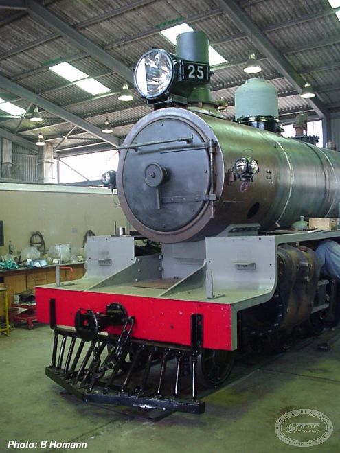
The smokebox has also been test fitted to the frames, and with the cylinders and running boards on, make the locomotive look a lot closer to completion.
For fiscal reasons (i.e. the $$ are going to run out), work at Panorama and Mt Barker is scheduled to finish within the next few weeks. This will mean that all the bits are then to be moved north, where it is intended that all outstanding work will become a volunteer project. There will be more details on this when plans are made clear.
Part 26: Steam test of the boiler—June 2002
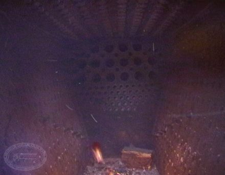
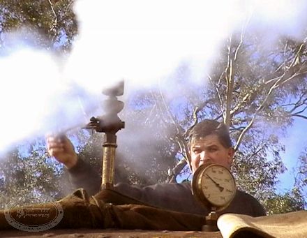
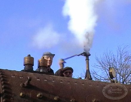
One of the most pleasing events in recent weeks has been the culmination of work on the boiler. Hydraulic testing of the boiler showed a few weeps, as was largely expected. Caulking was carried out where required, and the boiler then underwent a warm hydro test, with steam borrowed from SteamRanger's loco 621, probably the first and last time a 620 and an NM are connected together!
The boiler was shifted outside the shed, a rather tricky operation due the the limitations of the crane available, and with great trepidation a fire was lit. The fire was gradually built, with the pressure easing up to just over 100psi. One of the holes in the boiler that needed to be sealed was the mount for the whistle, and naturally the best option was to fit the whistle. Thus, for the first time in over 30 years, the sound of an NM whistle rang out over the hills. The hills in this case were foreign from the NM's native Flinders Ranges.
Listen to audio of the whistle: a short whistle
And a long whistle
It is expected that the final work to be done on the NM while it is at Panorama will be completed this week (17-21 June), and that the engine unit will then be sent to Port Augusta for completion by volunteers. Even with the volunteer labour, more money is still required to get the loco ready to put on a train.
Part 27: Installing boiler and wheels—July–September 2002
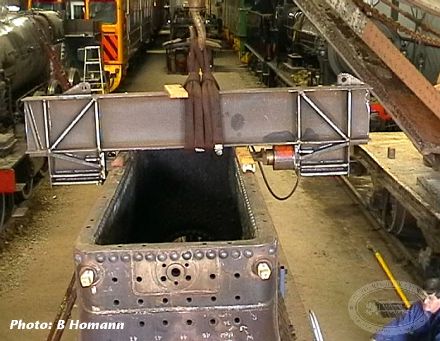
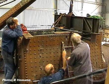
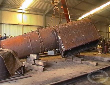
Since the last update significant milestones have been achieved, with the boiler being installed on the loco frame in a day of trucks and cranes which attracted quite an audience.
Following that, the majority of effort was concentrated on the driving wheels and axle boxes. Steamranger did the final boring of the axle boxes at their Mt Barker depot. Because of some problems with crown says in their Rx locomotive, our people assisted with the machining of new crown stays for that, to enable their machinist/steam fitter Ron Williams to get on with our axle boxes. In this way both jobs progressed as fast as was possible.
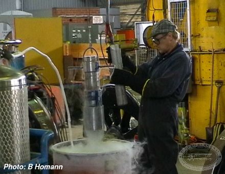
With some initial trepidation, the crank pins were immersed in liquid nitrogen and installed in the wheels. On the same day, the valve liners were installed using the same cold technology.
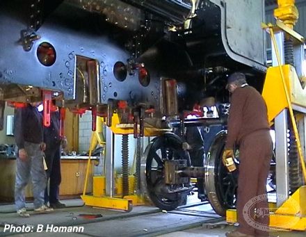
The wheely good news is that on 9 October 2002 the driving wheel sets were installed in the frame. The use of four electric jacks hired at very reasonable cost from All Transport Crash Repairs to elevate the frame made the job quite straightforward. With a considerable gallery and workers swarming over the wheel-sets, the scene was probably the busiest "cast of thousands" day on the job so far.
Part 28: Reassembly—October 2002
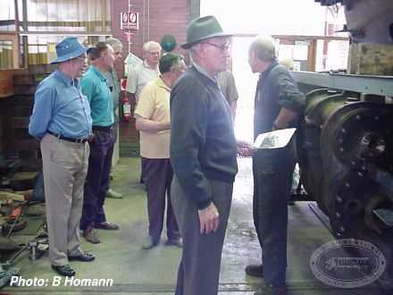
In October, a group of retired railway employees visited the works, and inspected progress on NM25.
Part 29: Trials—June 2003
The loco was scheduled to go to Port Augusta on 26 April 2003 for its official commissioning ceremony. Despite valiant efforts by a number of volunteers, problems with the hydrostatic lubricator and oil feed pipes caused the party to have to come to Quorn instead. The official train was headed by T186. NM25 was coaxed down into the yard for the ceremony. The lubricating problems were, despite extensive cleaning, residues of rubbish in the lubricator and pipes.
In the next weeks, all components were taken apart yet again. The lubricator was totally dismantled, boiled for several days in a caustic bath and then steam cleaned. A page full of jobs noted during the commissioning attempts have been attended to, and late in the evening of 18 June 2003, the loco was test moved in the Quorn loco depot. Despite further minor problems, the situation was sufficiently promising to operate a light engine trial to Woolshed Flat the next day.
This was accomplished, with the lubricator working perfectly. Some steam leaks showed up around the piston rod metallic packing covers, but rectification was easy once things had cooled down.
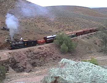
On 20 June 2003, NM25 hauled a test train from Quorn to Stirling North and return. The Traffic department had arranged for a pick up of crushings from the rock crushing plant at Mundallio, and Loco needed more firewood sleepers, so it became a work train. Interspersed with stops to check bearings, and the work train requirements, the trial progressed very satisfactorily. At a photo run by at Dog Crossing, the steam-boat type whistle echoed beautifully from the surrounding hills. Unfortunately the rebuild project manager, John Lyas, could not be in attendance due to the demands of his current employment. We let him listen in on the stack talk via the mobile phone as NM25 blasted out of Stirling North, back toward Quorn. This loco has quite a loud bark, despite its size, and will sound terrific on a cold winter’s night up in the Pass.
A long day was finally concluded when our work train slipped into Quorn under cover of darkness at around 7.30PM. There was not a solitary soul there to welcome us back home.
Whilst the job list has been mostly crossed off, further minor issues developed during the trials, so there is still close to a page of details to attend to. However, it is getting very close to the time when NM25 will once again be at the head of a passenger train.
Part 30: More trials—August 2003
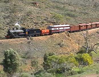
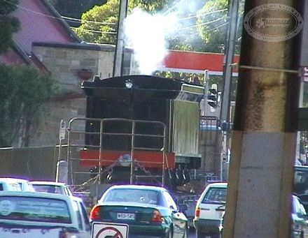
On Tuesday 12 August 2003, NM25 was put through a close to full load trial from Quorn to Port Augusta and return. The load was diesel-electric locomotive NT76 (to provide additional tonnage and backup power if required) and most of the operations SAR consist. Load was around 180 tons. The trial looked like being given a severe work out right from the beginning, with heavy rain falling as the train was marshalled. However, by departure time the rain had stopped, and the whole trial was conducted in overcast but dry conditions. Various delays were caused by lubrication problems, but all were manageable in the field.
The loco appears to be steady on its feet, with little tendency toward slipping, although wet rails may have been a different proposition. It also has a very throaty bark which will enable it to be heard comfortably from the train, and for miles lineside.
The results of the trial are a better understanding of the firing requirements, and a further few jobs to add to the list that has, despite some hiccups, been actually diminishing.