Part 23: Boiler squeezing—March 2002
The firebox fish bellying, which had caused a lot of headaches (and would have prevented the boiler going back into the frames), now appears to have been cured. Initially, we had tried a 20 ton squeeze on the foundation ring area, but found that we were not achieving yield point for the material. As our first estimate of the effect of the rest of the boiler was clearly not right, we sought help from our friendly finite element analyst. The compute showed the stress effects going further into the boiler, (and to a minor degree, appearing a long way from the point of application). The analysis predicted about 30 tons being required.
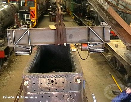
Another helper provided a set of detailed calculations and sketches for a 40 ton capacity squeeze frame. In effect this is like a giant hydraulically driven G clamp.
With some trepidation, the first squeeze was applied to the centre of the foundation ring. Careful measurement of hydraulic pressure, and boiler deflection were carried out as the load was gradually increased. In effect this became a stress/strain diagram which enabled us to determine when the boiler ceased behaving elastically, and began to yield. It was interesting to note that the person operating the hydraulics could "feel" the change from elastic to plastic, this being confirmed at the next measurement step.
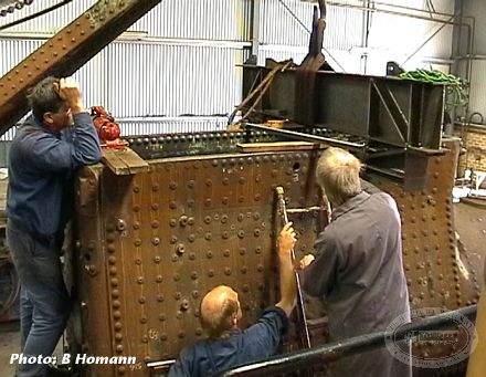
Several squeezes were required, sometimes using a piece of rail to spread the load on one side to direct the yield to one side only. The final result is a remarkably straight foundation ring, which is smaller than the width of the frame insides. It is probable that a few rivet heads will need to have a bit removed when it comes time to fit the boiler to the frame.
The new longitudinal stays have all been fitted and adjusted for length.
We are now, finally, at the point where the firebox tube nest can be welded into place.